AToM Features
- accurate method of moments core for 3D planar and wire structures
- characteristic mode decomposition using Arnoldi and QZ method
- advanced modal tracking based on adaptive frequency sweep
- Multilevel Fast Multipole Method for treating of electrically large structures
- utilization of the source concept
- optimal antenna design
- pattern / feeding network synthesis
- accept other codes from the community - open architecture
- graphical user interface
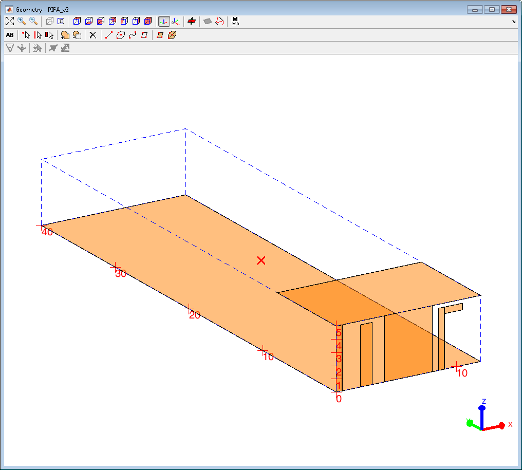
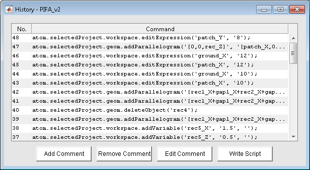
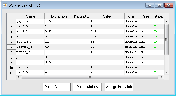
Graphical User Interface (GUI) in MATLAB
The AToM can be controlled either from script, command line or GUI as shown below: DesignViewer, HistoryList and WorkSpace.
Modal decomposition
The decomposition is based on Characteristic modes (CM), which results from weighted eigenproblem involving the method of moments complex impedance matrix Z = R + jX:
 ,
,
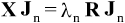
where Jn are characteristic (eigen) currents and λn their eigenvalues which represents reactive power of modes.
Contrary to the well known (internal) modes of cavity resonators, the CMs may be interpreted as external - radiating - modes of an antenna. They are excellent for deep understaning of physics of radiation, pattern synthesis, feeding network synthesis and optimalization of radiating structures.
Simple, but illustrative example is shown below. It represents CMs at bow-tie dipole where we see number of different eigencurrents of which the total current is formed once the feeding is connected. Basically there exist dipole-type and loop-type modes. The graph represent reactive power of modes, crossing 180 at resonance.
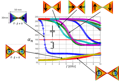
The accuracy of modal decomposition is highly sensitive with respect to treatment of singular integrals in the Method of moments. The AToM package is doing very well as seen from comparison with other softwares. The picture below shows eigenvalues of spherical shell evaluated by different solvers and compared to exact analytical solution.
Structural decomposition
Similarly to structural decomposition in mechanical engineering, it is possible to physically separate the currents at antenna to decide:
- what part of a radiator stores significant portion of energy
- what part radiates well
This approach is excellent for synthesis of reflectarrays and can be even combined with CMs to form so-called sub-structure modes.
The implementation in AToM will allow user to select part of the structure and evaluate amount of stored energy and radiated power.
Feeding synthesis
 The Characteristic modes concept is very efficient for feeding synthesis of antennas. Since the modes depends only on frequency and geometry of the radiator, the excitation presents independent variable. The required calculation is thus very effective because modal decomposition is performed only once. Knowledge of modal characteristics allows user to design the feeding points in orded to "turn on" or "turn off" selected modes. This may result in completely different behavior of the structure.
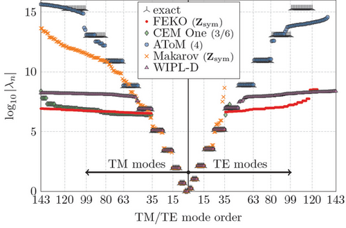
As an example, the meandered dipole at the left was optimized for lowering its radiation quality factor. The characteristic modes and the external world represented by feeding are connected through coupling matrix, denoted here beta.
The lowest achievable Q factor was finally found by the FOPS optimizer and it involves two in-phase feeding points located as shown at the lower picture.
Another example on feeding synthesis was demonstrated in the area of MIMO antennas using polarization-diversity. We refer to online paper on modal analysis of dual-PIFA antenna.
In glance, the feeding synthesis can be used to effectively manipulate the following quantities:
- Stored electric / magnetic energies, radiation quality factor
- Radiation pattern (multiple beams, different polarizations)
- Radiation efficiency
- Far field cross-correlation
- Near field distribution
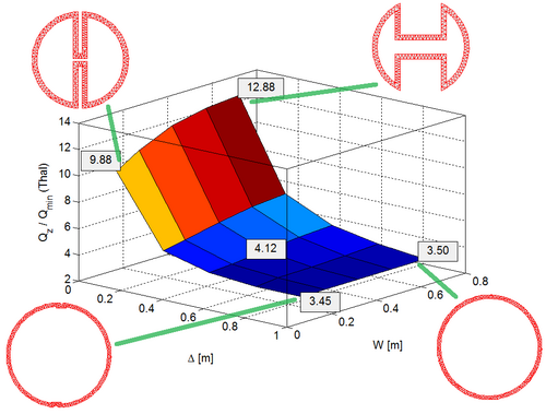
Optimization
AToM is accompanied with powerful optimizer named FOPS. Picture below show optimization of antenna shape (two geometric parameters) for minimum Q. Outer dimensions (circumscribing sphere) are kept fixed.